Concept Design Report
Mirror segment support system
California Extremely Large Telescope
Steve Gunnels
Paragon Engineering, Tehachapi, CA
93561
March 8, 2001
CAD
drawings (1-8) and figures (1-16)
for this report
1. INTRODUCTION
A concept
design has been developed for the mirror segment support system for the California
Extremely Large Telescope. The work
has entailed considerable finite element analysis and numerous CAD layouts.
A total of 62 finite element models, many with multiple load cases,
were created and solved. The most important of these results are summarized
below with the aid of pertinent FEA graphics plots. The CAD drawings which best show the current
design are included in this report as figures “CAD-1"
through “CAD-8". During the
period of performance of this work, informal weekly reports were submitted.
They are also included in the addendum of this report along with vendor quotations
and other miscellaneous background information.
2. AXIAL SUPPORT SYSTEM
As shown
in drawing CAD-1, the segment was specified
as hexagonal, 1 m across points, 45 mm thick and made of Schott Zerodur glass
ceramic. In addition, it was required that the support system be designed
and optimized with 18 axial support points and a lateral support that worked
from the back surface (no holes or pockets in the mirror).
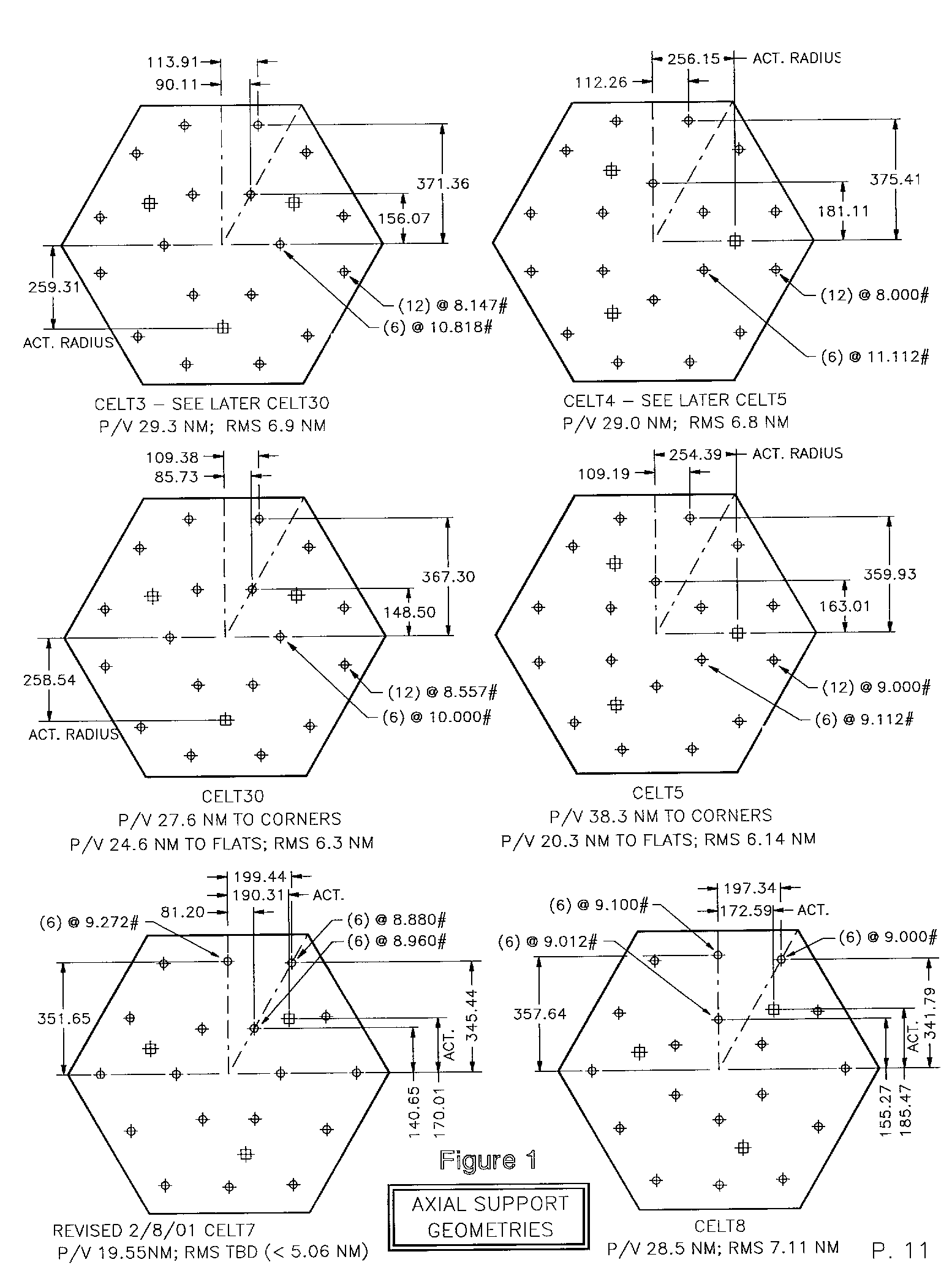
For 18 supports
of a hexagonal segment the smallest fundamental geometry consists of a 1/12th
segment wedge indicated by the phantom lines in Figure
1, “Axial Support Geometries”. Such
a system includes 4 possible topologies, analyzed initially with finite element
models CELT3, CELT4, CELT7, and CELT8 also indicated in Figure
1. (Note that the small round symbols are support locations, the larger
square symbols actuator centers).
2.1 Surface distortion and support topologies
During the
finite element optimizations it was recognized that a support which defines
the minimum peak-to-valley (p/v) surface distortion would not necessarily
also define the minimum rms. This
is particularly true for the two topologies without supports near the corners.
In other words, by allowing the corners (with a relatively small area)
to droop somewhat, the supports can do a better job of minimizing deflections
of the rest of the segment, which has a much larger area.
Therefore two additional optimizations are included in Figure
1 - CELT5 based on the CELT4 topology and CELT30 based on the CELT3 topology. Note that in both cases the rms lowered even though the peak-to-valley
increased.
Topologies
CELT(3 & 30) and CELT(4 & 5) define actuator centers which are rotationally
symmetric with respect to the hexagon while topologies CELT7 and CELT8 do
not. It was initially assumed that this lack of symmetry would be undesirable
due to complicating system design and increasing hardware cost. However, the minimum-rms topology is currently
the unsymmetric CELT7. (Its final
optimization yielded a p/v surface distortion of 19.6 nm. Although not yet calculated, the rms will certainly
be a little less than 5.06 nm, an earlier result with a slightly higher p/v.)
CELT7 has been more highly optimized than the other geometries. However,
it is expected that with further optimization of the symmetric topologies
they will define an rms surface distortion which is still about 1 nm greater
than CELT7. This results from the fact that the CELT7 topology
has two supports on a radial line to the corners of the hexagon and it therefore
does a better job of controlling the corners. In summary, there is a trade
to be evaluated of the (approximate 1 nm) performance gain against potential
complications which might result from the unsymmetric geometry.
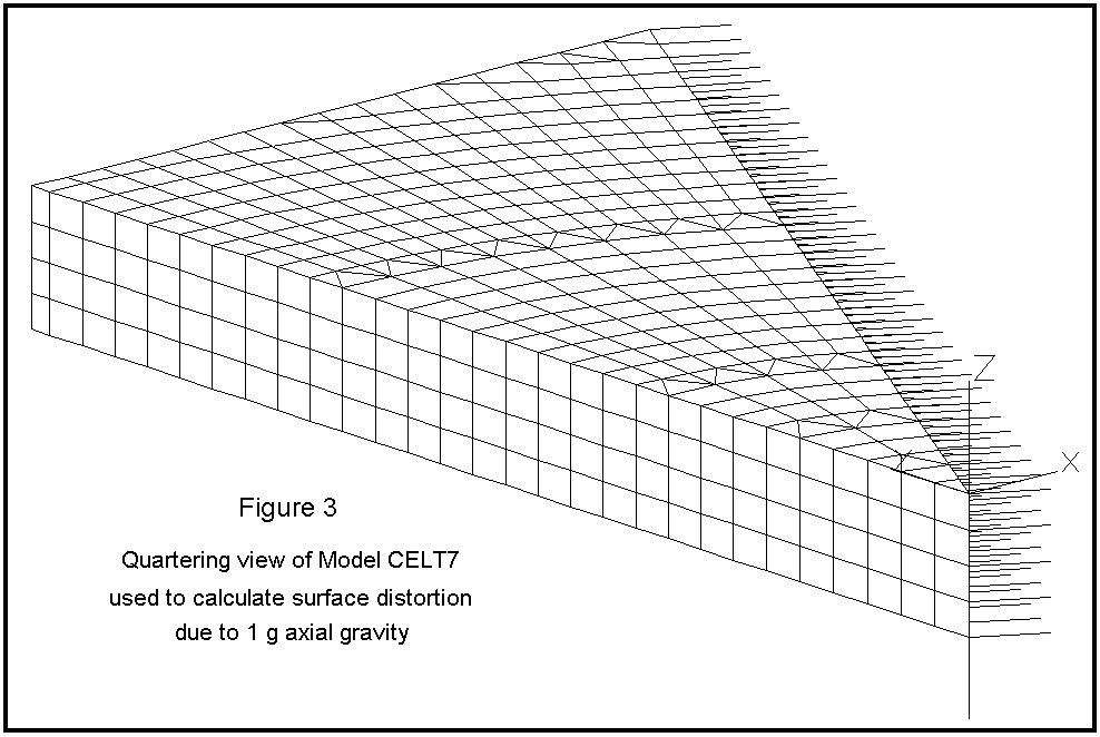
2.2 Finite element analysis
Three-dimensional
solid elasticity (brick) elements were used to calculate the surface distortion
due to axial gravity. One of the models (CELT7) is shown as Figure
3. Nodal restraints were used to define symmetry
boundary conditions in the YZ plane and beam elements end-released to define
only axial stiffness were used on the skewed plane as shown. Nodal loads,
although not shown, were used to support the model from below, while axial
gravity element loading was applied directly to the brick elements. The single
vertical (axial-only) beam element at the origin was used to verify the vertical
balance of the model (equilibrium defines that it should have zero force).
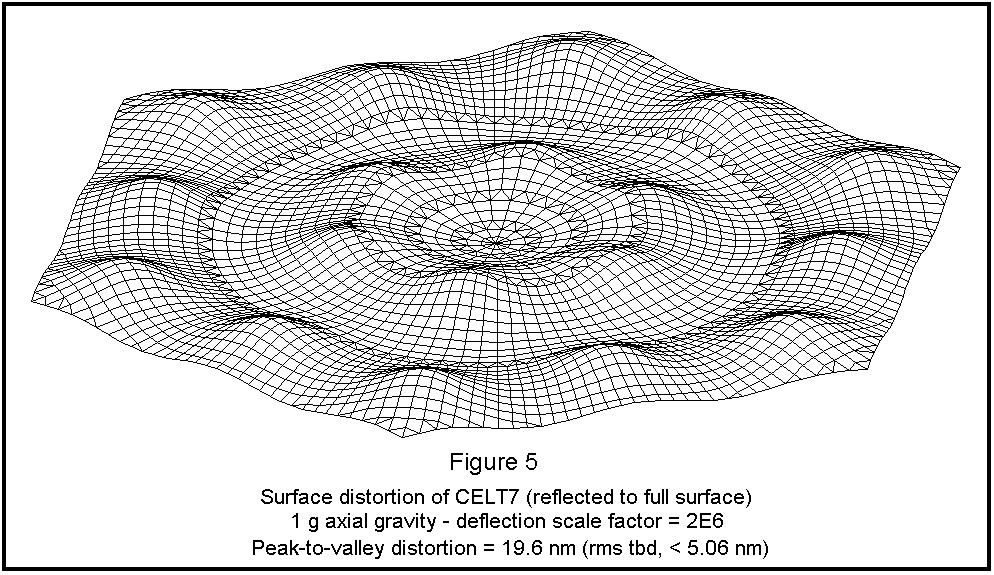
The optimizations
were done by a combination of moving nodal loads and varying their relative
magnitudes in order to minimize the peak-to-valley surface distortion.
A highly exaggerated deflected plot of the surface shape was generated
by mirror/rotating the 1/12th segment surface around the Z axis.
Shown as Figure 5, the print-through
from each of the 18 supports is apparent.
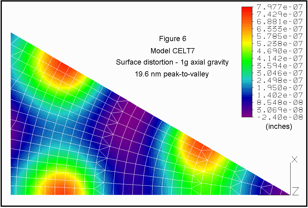
The dithered color contour plot directly from CELT7 is shown as Figure
6. A summary of the results for
all 6 geometries follows:
|
Surface distortion due to 1 g axial gravity |
|||
|
Geometry
(model) |
Peak-to-valley,
nm |
RMS,
nm |
Comments |
|
CELT3 |
29.3 |
6.9 |
Symmetric. Not highly optimized. |
|
CELT30 |
27.3;24.6 |
6.3 |
CELT3 topology better optimized. |
|
CELT4 |
29.0 |
6.8 |
Symmetric. Not highly optimized. |
|
CELT5 |
38.3;20.3 |
6.14 |
CELT4 topology better optimized. |
|
CELT7 |
19.6 |
(< 5.06) |
Not symmetric. RMS not calculated. Most highly optimized. |
|
CELT8 |
28.5 |
7.11 |
Not symmetric. |
2.3 Axial support hardware
The axial
support hardware was designed to be inexpensive to manufacture in large quantities.
Assembly views are included in drawings CAD-1and
CAD-2, with detailed views in drawings CAD-4
and CAD-6.
As shown, each system includes:
2.3.1 18 rod flexures (ref CAD-2
and CAD-6), an epoxied assembly comprised
of 2 aluminum sleeves, 1 aluminum axial support pad, 2 piano wire flexures,
and a silicone pad. The silicone pad
is glued with silicone adhesive to the axial support pad and later to the
back of the segment with the same silicone (ref weekly report, “Assembly Plan”).
The rod flexure serves to stiffly transfer axial load to the segment
while accommodating tilt motions and manufacturing tolerances without inducing
significant deflections of the segment. Each
rod flexure assembly weighs only about 0.5 oz. so that deleterious effects
due to self-weight under lateral gravity are also negligible.
2.3.2 6 tri-plates (ref CAD-2 and
CAD-4), a ½" thick triangular aluminum
plate which acts as a load spreader from the whiffletree ends to the rod flexures.
The tri-plates are laser cut, Blanchard ground, and production drilled and
tapped as shown.
2.3.3 6 tri-plate pivots (ref CAD-2
and CAD-6), an epoxied assembly that connects
the tri-plates to the ends of the whiffletree beams.
This is done in a way that assures no bending transfers to the segment
due either to axial force or moment errors on the tri-plates that might result
from horizon gravity. This is discussed in some detail in appendix
report “Surface distortion due to Tri-plate Pivots under horizon gravity”.
2.3.4 3 whiffletrees (ref CAD-2),
a mechanical assembly with (2) 1/4" side plates and 2 whiffletree blocks. The assemblies are aluminum.
2.3.5 2 whiffletree pivots (ref CAD-2). Baselined as TRW Lucas Aerospace “Free-Flex Pivots”, they serve
to (somewhat) stiffly apply the actuator force to the whiffletrees with only
small moment error. Due to their significant cost and less than ideal performance,
these will likely be custom-designed during the Preliminary Design phase.
With approximately
1,300 support systems (1,080 active units plus 1/6th rotated spares plus 40
actual spares), there are a total of 23,400 rod flexures, 7,800 tri-plates
and tri-plate pivot flexures, and 3,900 whiffletrees and whiffletree pivots. Additional construction and assembly details
are described in the weekly report “Assembly Plan” in the appendix.
3. LATERAL SUPPORT SYSTEM
With the
lateral support at the back surface of the segment, a moment exists under
lateral gravity due to the axial eccentricity of the lateral force with respect
to the c.g. plane of the segment. A
number of methods and geometries were evaluated for the lateral support system.
These included:
Three supports
at the back surface (at the actuator locations) using the axial supports to
react the moment.
A single
central support at the back surface using the axial supports to react the
moment.
A “unified
support” in which a single system of struts is used for both the axial and
lateral support functions.
The above
methods were shown to exhibit very large surface distortion due to significant
moment existing in the segment over relatively large distance scales. Peak-to-valley distortion ranged from many
hundred nanometers to as high as about 6 microns. The next method tried employed a single central support at the back
surface using levered counterweights in close proximity to the load application
to react the moment. It was discovered
that the surface distortion was highly dependent on the local geometry for
the lateral load application as compared to that for the moment compensation.
Refining these geometries progressively (using 7 iterations) reduced
the peak-to-valley surface distortion from 143 nm to 10.5 nm.
While the
lateral support system provides a soft definition of the mirror segment rotationally
about the local optic axis, this will likely not be adequate in operation.
The segment needs to be positioned rotationally with modest accuracy
to achieve optical tolerances. It is anticipated that a reasonably stiff tangent
arm, perhaps including a small electromechanical actuator, will be included
during the preliminary design phase. The
current rotational definition via the silicone pads at the lateral support
is sufficiently soft to accommodate significant rotational adjustment.
3.1 Axisymmetric design
At this
point it was recognized that there is one additional important constraint
on the lateral support system. All
segments except those on the central vertical plane of the mirror array experience
compound lateral force components. That
is, for these segments as the telescope rotates from zenith toward horizon,
the lateral gravity vector rotates in a plane that is skewed with respect
to those segments. And the magnitude
and alignment of the skew depends on the location for the segment within the
mirror array. Therefore, the lateral support must be “axisymmetric”, or work
for any rotational orientation of lateral gravity with respect to the local
optic axis for the segment.
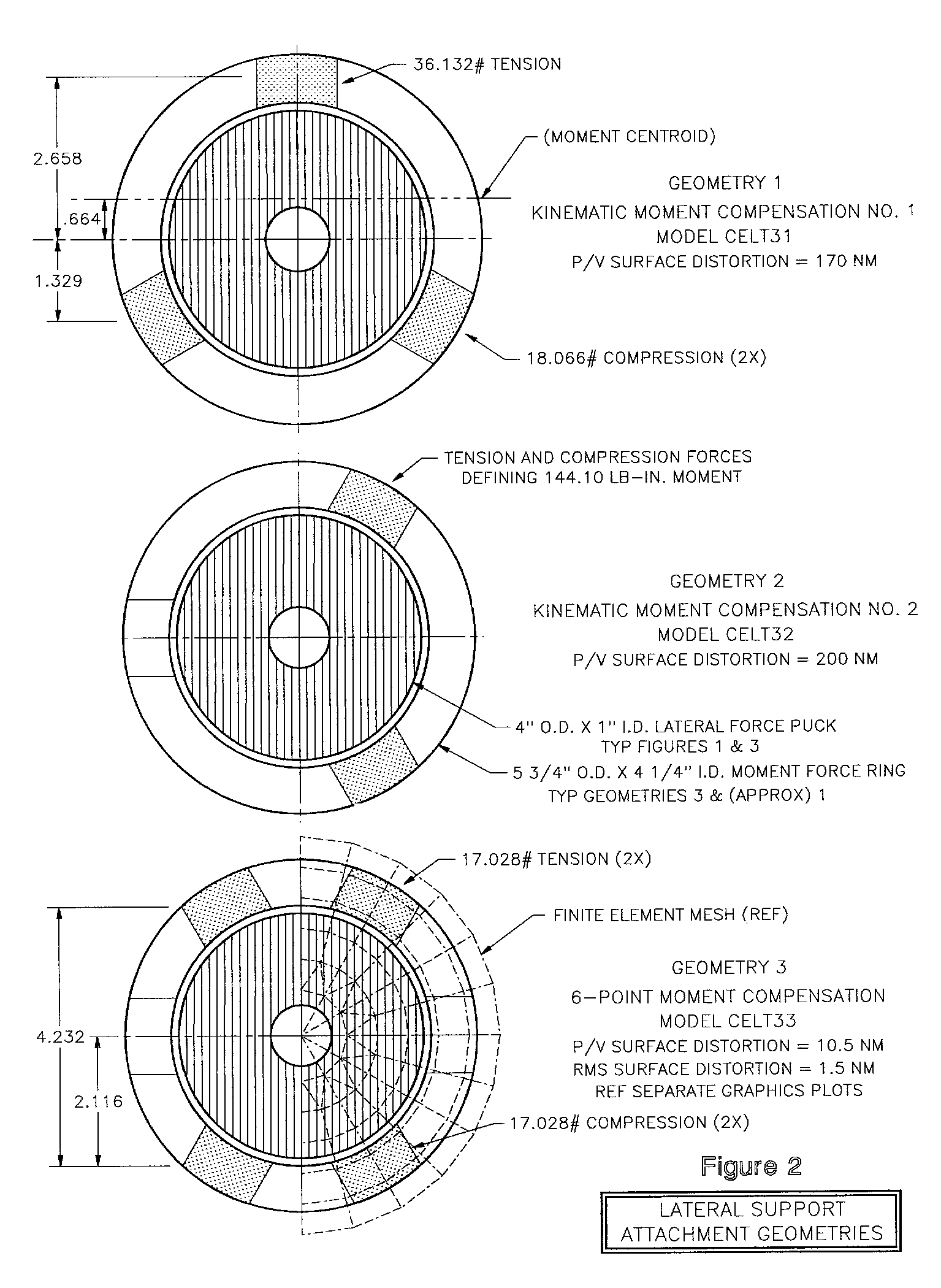
The method
chosen to achieve this was simply that of attaching a counterweight (not levered)
directly to the back of the segment. Two kinematic attachment geometries were
initially considered, shown as “geometries 1 and 2" in Figure
2. They were found to cause relatively
large surface distortion (the reasons are described in the weekly report “Axisymmetric
Lateral Support System” in the appendix). However, if the counterweight attaches
with 6 silicone pads, it would apply the moment compensation forces with a
very similar geometry to that of the earlier levered counterweights. Although
slightly locally over constrained, the pad design was shown to be sufficiently
compliant to keep surface distortion due to thermal and manufacturing effects
to a negligible level (also described in the weekly report).
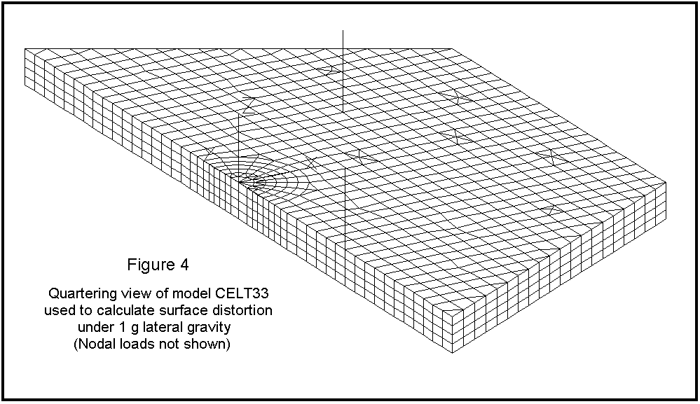
3.2 Finite element analysis
Brick elements
were also used to calculate the surface distortion due to the lateral support.
Shown as Figure 4, the final lateral
support model CELT33 used nodal loads (not shown) to apply the lateral support
force and moment compensation forces. Lateral
gravity element loading was used to apply the lateral load directly to the
brick elements. A half-segment model
was used due to load and structure symmetry.
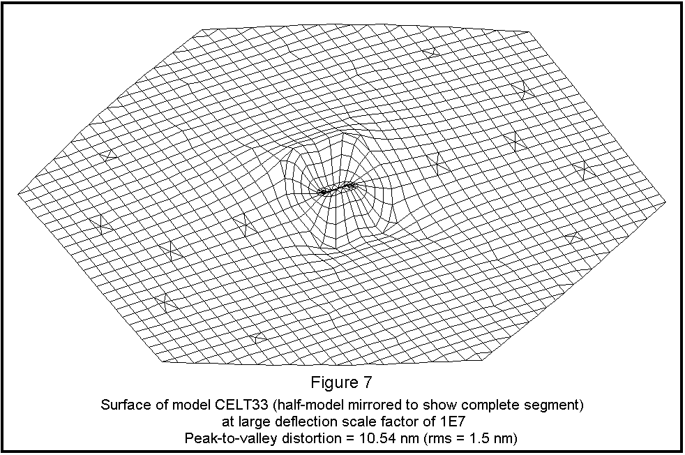
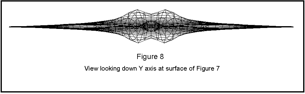
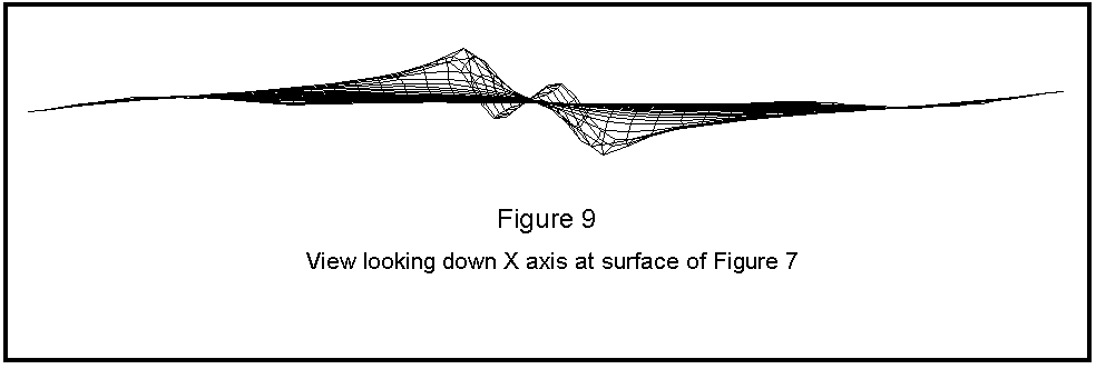
The surface
distortion of the final optimized design is shown highly exaggerated in Figures
7 through 9, which have been mirrored to a full segment. As shown there, the surface distortion due
to 1 g lateral gravity was calculated as 10.54 nm p/v, 1.5 nm rms. Figure 10
is a dithered color contour plot of the surface near the support.
This local view was provided because a larger-scale view would be misleading
due to relatively large tilt of the model which was an artifact of the model
restraint.
In addition
to calculations of surface distortion due to the lateral support, models CELT35
thru CELT40 were used to predict and optimize the structural performance of
the disk flexure. The resulting favored
design exhibited the following properties:
|
Disk Flexure Structural Properties |
||||
|
Model (thickness) |
Material |
Axial
Force Error
at 0.6 mm |
Radial Defln
@ 1g, in. |
Von Mises
Stress, ksi |
|
CELT40 (.025) |
17-7ph s.s. |
.54 lb |
.0041 |
21.6 |
Model CELT35
(.020 in. thickness) was also tested for non-linearity. After the full .6 mm axial motion the axial
stiffness increased by only 10.4%. It
is therefore believed that all of the considered designs will exhibit acceptably
low non-linearity.
One important
structural feature of the disk flexures is their strength, since they are
thin and must radially support the approximate 180 pound weight of the segment
and moment counterweight. A crude
manual calculation was performed using American Institute of Steel Construction
(AISC) criteria. By this criteria,
and with .025 in. thickness, these designs might not be adequately stable.
However, the geometry is not at all similar to the kinds of beams and
structures for which the AISC formulae were developed.
A physical stability test was therefore conducted of the CELT40 design. The results were promising, although not conclusive because the
tested material was a little thicker (.031 in. as opposed to .025 in.) but
considerably lower strength than the design flexure. Therefore, a more definitive test should be conducted during the
preliminary design phase.
3.3 Lateral support hardware
The hardware
for the axisymmetric lateral support described above and modeled in CELT33
is shown in drawings CAD-1 and CAD-3
through CAD-5. It consists of:
3.3.1 Moment counterweight, a precision weldment of the 14#
annular counterweight and counterweight extension tube. The annular counterweight (CAD-4)
is a production lathe part. Using
a standard hot rolled steel tubing size, the i.d. and o.d. are sized, the
shallow recess machined, then it is parted off with a plunge cut. The counterweight extension tube (CAD-5)
is made from 5" o.d. x .065 wall CREW (cold rolled electric welded) mild
steel tubing. The part is precision cut to length, the slot
is milled, then two access holes made by hole saw and the 6 small holes drilled
using a drill jig. The milled slot
is sufficiently long to allow sliding the moment counterweight back to disconnect
the disk adapter fitting to the end of the 3 ½" square lateral support
tube. The 5" diameter counterweight
extension tube, with its thin wall and minimal clearance to the tabs on the
moment force ring helps minimize distortion of the ring during torquing of
the six small screws.
3.3.2 Moment force ring (CAD-3
and CAD-5), glued to the segment with .16
in. thick Dow 3145 silicone RTV. It serves to connect the moment counterweight to the glass and distribute
the moment forces in a controlled way. Made from invar, it is premachined on a lathe then the integral
tabs are N.C. milled.
3.3.3 Lateral force puck (CAD-3 and CAD-5), glued to the segment with .12 in. thick Dow 3145 silicone
RTV. It transfers the lateral shear
force from the disk flexure to the segment to support the horizon gravity
component of the segment weight. It is made from invar.
3.3.4 Disk flexure (CAD-3), the
center of which screws to the end of the lateral support tube while the three
ends screw to the lateral force puck. It
transfers the lateral shear force from the lateral support tube to the lateral
force puck while isolating this system from axial forces.
Under the full +/- .6 mm travel of the axial actuators the axial force
error from the disk flexure defines surface distortion in the segment which
is acceptably small. The disk flexure
is made from .025 thick 17-7PH stainless steel using wire edm. Actually, approximately 50 disk flexures can be wire electrical-discharge
machined simultaneously and in one setup so that these parts, although complicated,
will be inexpensive.
3.3.5 Disk adapter fitting (CAD-5),
which connects the disk flexure to the end of the lateral support tube. The final shear-type friction connection minimizes assembly axial
force error in the disk flexure.
3.3.6 Zenith counterweight (CAD-3
and CAD-4), mounted to the lateral support
tube with small flexures (not yet designed) and connected to the annular counterweight
via a tie rod and transverse pin. It supports the zenith gravity component of
weight of the moment counterweight and moment force ring and thereby eliminates
surface distortion of the segment from this source.
4. Miscellaneous analyses and results
In addition
to the axial and lateral support optimizations summarized above, numerous
related calculations were made which relate in various ways to the support
system. A brief summary follows:
4.1 Warping harness influence functions
Model CELT34
was created to determine the segment distortion due to applying 1 N-m moments
around: a.) the whiffletree pivot, b.) the tri-plate pivot parallel to the
X axis and c.) the tri-plate pivot parallel to the Y axis. Based upon the CELT5 topology, the results
were reported and are to be used by UCSC for estimating what effects can be
corrected by the warping harness.
4.2 Rotation of segment due to disk flexure
Model CELT41
was used to determine whether the disk flexure defines a rotation of the segment
due to its geometry under a pure lateral load. It was shown that it does not.
4.3 Surface distortion due to thermal effects
of lateral support
Models CELT42,
43, 44 and 48 were created to determine distortion due to the large bonded
lateral support fittings under thermal loading (the -60 deg F differential
from the fabrication environment to the minimum operating temperature) .
The distortion was estimated to be 7.1 nm p/v, and approximately 1.6
nm rms. It was also demonstrated that it is both important
to use invar for the fittings and silicone adhesive to soften the distortion
effect. Surprisingly, CELT48 indicates
that it is slightly better to glue the invar lateral force puck continuously
to the segment (without an annular interruption in the silicone).
4.4 Surface distortion due to rod flexures
under maximum tilt of segment
Model CELT45
showed that the surface distortion under maximum segment tilt (due to one
actuator fully retracting .6 mm, a second fully extending .6 mm) was 5.65
nm p/v, 1.34 nm rms. Since this is a highly unlikely operating condition,
it can be concluded that the rod flexures are adequately compliant in bending.
The results are described in more detail in the weekly report dated December
28, 2000. In addition, models CELT46 and CELT47 demonstrated that the rod
flexures, with small diameter piano wire flexures at each end, are considerably
more efficient than using a solid-diameter rod for the full length of the
assembly.
4.5 Surface distortion caused by eliminating
zenith counterweight
Models 49
and 50 were used to determine the increase in surface distortion if the zenith
counterweight is eliminated and the moment counterweight zenith gravity self-weight
is supported directly as a somewhat concentrated load at the center of the
segment. The result was that the distortion
increased from 21.5 nm to 28 nm p/v, or 5.06 nm to 6.7 nm rms. The results are described in more detail in
the weekly report dated January 22, 2001.
4.6 Surface distortion due to tri-plate
pivots under horizon gravity
Models CELT51
through CELT53 were used to optimize the piano wire tri-plate pivots and to
show that, properly designed, they contribute virtually zero surface error.
The analysis and results are described in detail in the weekly report
dated January 27, 2001. The tri-plate pivot flexures and rod flexures
should be stability tested as a system in the Preliminary Design phase, since
this is difficult to calculate accurately by theoretical means.
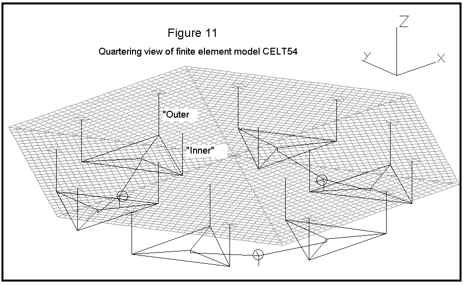
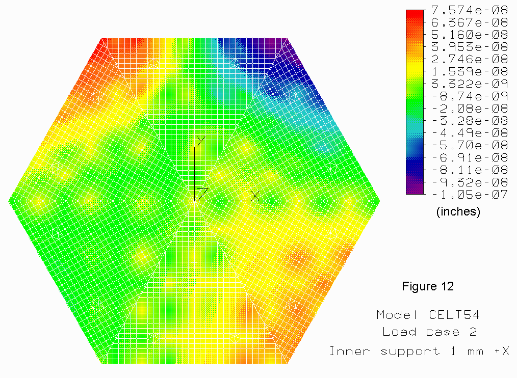
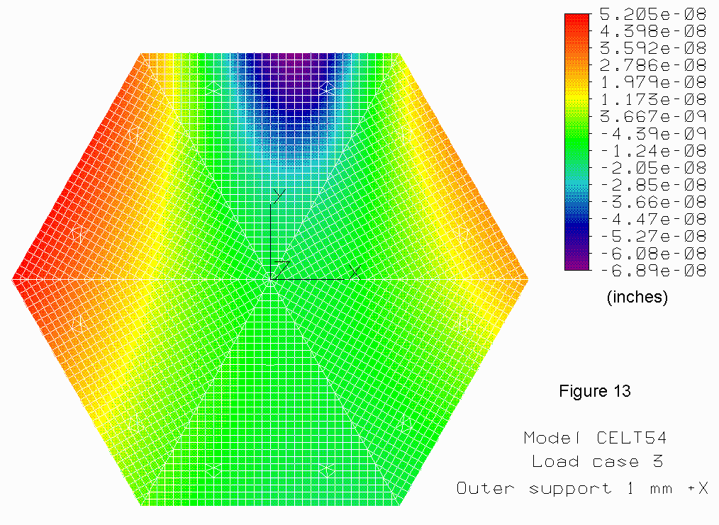
4.7 Error sensitivity analysis
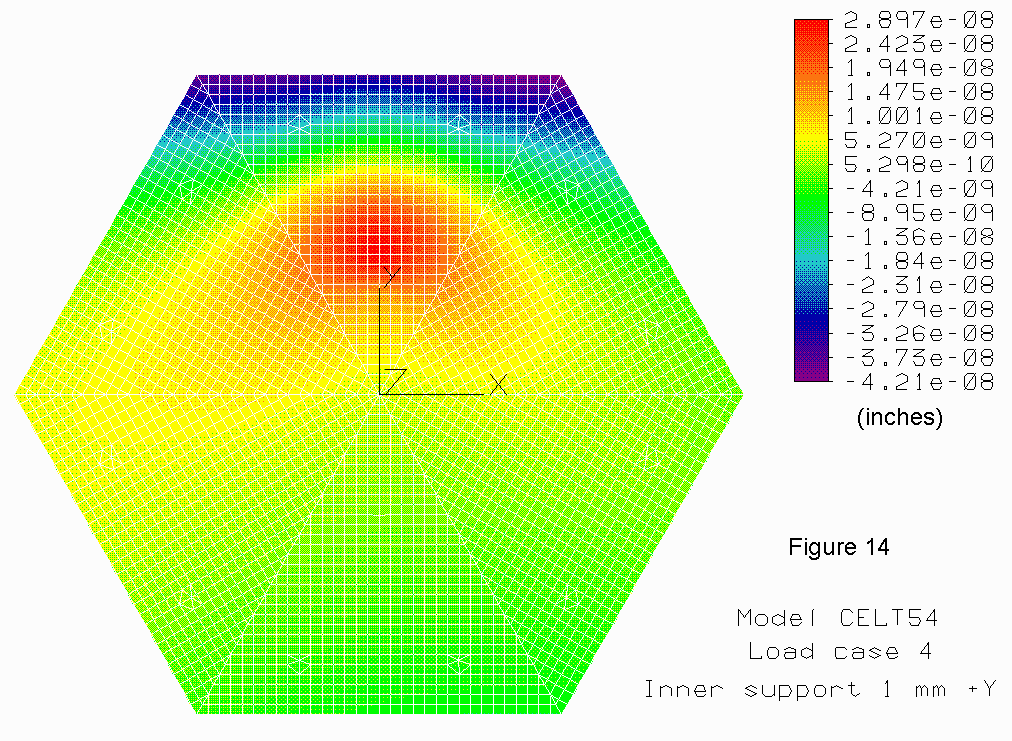
Models CELT54
through CELT58 were created and solved to determine surface figure error sensitivity
to manufacturing and assembly errors. Model CELT54 is shown as Figure 11
below. The analysis is described in detail in the weekly report dated February
1, 2001. Dithered color contour plots are included for load cases 2 through
5 as Figures 12 through 15 below.
Graphics plots for other load cases are not included due to large tilts
which are artifacts of the model restraint and which mask the actual deflected
shape of the segment.
4.8 Surface distortion due to wind pressure
gradients
Models CELT59
through CELT62 were used to calculate surface distortion due to linear pressure
distribution (two orthogonal directions) and one higher order effect [P =(
2.405 x R^2) - 1]. Based upon a very
high peak pressure of 1 psi, the results are linear and scaleable to realistic
pressures the system is likely to experience. The results are described in more detail in
the weekly report dated February 5, 2001. The dithered color contour plot
for the higher order case is provided as Figure
16, since it is meaningful without tilt caused by model restraint and
support compliance. Although dynamic components of wind pressure cannot likely
be compensated by the mirror active support, steady and very low frequency
components likely can, and these results may be helpful in quantifying those
corrections.
4.9 Stiffness of the axial support system
The axial
support system has been designed to achieve a local first resonant frequency
of 60 Hz. This resonance would result if the axial deflection of the segment
under a purely axial 1 g load were .0027 in.
The calculated deflection under this load is:
| (Lucas pivot)* | .00180 in. |
| Whiffletree beam | .00006 in. |
| Triplate pivot | .00012 in. |
| Triplate | .00023 in. |
| Rod piano wire | .00013 in. |
| Rod | .00003 in. |
| Rod piano wire | .00013
in. |
| Silicone | .00009
in. |
| Total | .00259
in. |
*1/2"
Lucas pivot. A larger pivot, at considerably
higher stiffness, could likely be used. However, the ½" pivot would define lower surface distortion
due to extremes of actuator motion. A
custom designed pivot would also likely be stiffer. Since this entry is the dominant (most compliant) one, significant
gain might be made here during the preliminary design.
The local
first resonant frequency of the segment on its lateral support system has
been estimated to be 30 Hz.
4.10 Natural frequency and modeshapes
Although
not comprehensive, some initial modal analysis has been performed. Model CELT63
was used to calculate the axisymmetric bending frequency and modeshape for
the mirror on three supports at the actuator locations. CELT64 was used to
calculate free vibration modes. The mirror on three supports had an axisymmetric
bending mode frequency of 439 Hz. The
first four free-vibration modes were:
1. 337 Hz - First astigmatism (linear bending).
2. 337 Hz - (Orthogonal mode).
3. 536 Hz - Axisymmetric bending.
4. 719 Hz - Second astigmatism (linear bending).
4.11 Support system weight
A weight
summary of the support system as it is currently designed follows:
|
I. Axial Support System |
|
|
|
A.
Rod flexure pads - .013 lb |
x 18 |
.271 |
|
B.
Rod flexure rods - .03 lb |
x 18 |
.539 |
|
C.
Sleeve 2 - .0056 lb |
x 18 |
.100 |
|
D.
Piano wires |
|
.009 |
|
E.
Tri-plates (aluminum, ½") - 2.39 lb |
x 6 |
14.340 |
|
F.
Whiffletree blocks (aluminum) - .063 lb |
x 6 |
.375 |
|
G.
Whiffletree beams (aluminum, 2 - 1/4") - 1.65 lb |
x 3 |
4.941 |
|
Total weight, axial support system |
|
20.60 |
|
I. Lateral
Support System |
|
|
|
A. Lateral force puck (invar) |
|
.834 |
|
B. Moment force ring |
|
2.506 |
|
C. Counterweight extension tube (mild steel) |
|
3.500 |
|
D. Moment Counterweight |
|
14.169 |
|
E. Zenith counterweight |
|
5.478 |
|
F. Disk flexure |
|
.259 |
|
G. Disk adapter fitting |
|
.140 |
|
Total weight, lateral support system |
|
26.90 |
|
Total weight of Segment Support
System |
47.50 lbs (21.6 kg) |
The above
weight exceeds the specification by about 50%, but for good reason. Normally one would expect a lateral support,
acting at a single concentrated location, to be considerably lighter than
the axial support which supports the same weight but distributed over a large
area. Here the lateral support weighs
considerably more than the axial support as a result of the requirements of
acting at the back surface and being axisymmetric (i.e. due to the moment
and zenith counterweights). The budgeted weight requirement should be re-evaluated
during the preliminary design phase.
5. Surface distortion error summary
The following
is a summary of many of the calculated surface errors:
|
Surface Distortion Error Summary |
||
|
Comments, error source |
Peak-to-valley,
nm |
RMS, nm |
|
Axial support, 1 g axial gravity, CELT7 topology |
19.6 |
< 5.06 |
|
Lateral support, 1 g lateral gravity. |
10.54 |
1.5 |
|
Disk flexure axial force error at full .6 mm axial travel |
18.2 |
4.8 |
|
Thermal effect acting on lateral support, -60 deg F |
7.1 |
1.6 |
|
Rod and tri-plate flexures under maximum segment tilt |
5.65 |
1.34 |
|
Eliminating zenith counterweight (axial sprt, increase of) |
19.6 to 28 |
5.06 to 6.7 |
Surface
errors due to wind pressure gradients, manufacturing and assembly errors,
and other calculations resulted in scaleable information which is too intricate
to present in a simple table. In these
cases the individual sections of this and the weekly reports must be used.
6. Assembly plan and cost estimate
A concept
design level Assembly Plan and Cost Estimate have been developed. They are presented in detail in the appendix
weekly report dated February 24, 2001. A
brief summary follows:
|
1. Axial Support
System Hardware |
***553.31 |
|
2. Axial
Support System Assembly |
141.92 |
|
3. Lateral
Support System Hardware |
247.20 |
|
4. Lateral
Support System Assembly |
159.80 |
|
Total cost per segment |
$1102.23 |
*** Includes $314.70 for Lucas flex pivots,
which can likely be reduced in next design phase.
Many of
the above hardware costs came directly or indirectly from bids. The assembly labor times were gotten using
the typical “industrial engineering time/motion” technique, using a stopwatch
and going through the motions required for each task. The stopwatch times were increased by 50% to allow for unforseen
inefficiencies. In fact, the lateral
support assembly times were again doubled, since the part quantities are low
and being that conservative has only a small effect on cost.
On the other
hand, the estimate is based upon a concept design which is sure to change.
And it is very likely that some components (especially assembly labor)
have been overlooked. But it is the author’s opinion that if this
very simple hardware design is preserved through subsequent design phases
and a good job is done in the manufacturing phase, the support system cost
per segment should be well under the budgeted $2,000 per segment.
7. Conclusions
A concept
design has been developed for the mirror segment support of the California
Extremely Large Telescope. The axial and lateral support assemblies have a
somewhat unusual appearance due to the requirements of being manufactured
and assembled at very low cost and working entirely from the back surface. The current design has a good chance of meeting
the system requirements once a formal error budget is finalized. If the simple design is maintained through
future design phases and a good job is done during construction the support
system cost per segment will be under the budgeted $2,000 cost per segment.
Drawings and Figures for Report #16: Concept Design Report-Mirror Segment Support System-California Extremely Large Telescope, Steve Gunnels (March 2001)
| CAD-1 | CAD-2 | CAD-3 | CAD-4 |
| CAD-5 | CAD-6 | CAD-7 | CAD-8 |
| FIG 1 | FIG 2 | FIG 3 | FIG 4 | FIG 5 | FIG 6 | FIG 7 | FIG 8 |
| FIG 9 | FIG 10 | FIG 11 | FIG 12 | FIG 13 | FIG 14 | FIG 15 | FIG 16 |
Back to Reports and Technical Notes
Website maintained by Heather
Mietz, email: heather@ucolick.org